- Home
- Products
- Control Units
- Master Controller v3+
Master Controller v3+
The Master Controller V3+ is a multifunction industrial control unit, designed for automatic management of programmable heating processes.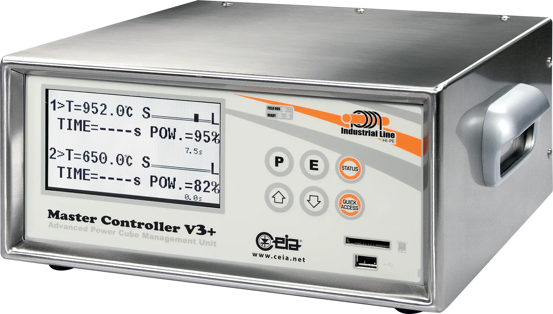
Key Points
The Master Controller V3+ is a multifunction industrial control unit, designed for automatic management of programmable heating processes for CEIA Induction Heating Systems. It plays a critical role in managing the induction heating process through advanced microprocessor technology. The Master Controller V3+ offers precise and reliable feedback and control of up to two independent heat stations as well as utilization of CEIA's line of accessory components, including wire feeders and gas diffusers.
Thanks to the optional Thermal Profile software, users are now able to input up to 20 programmable temperature and time segments per heating cycle for optimal control over the entire heating process. The Master Controller V3+ can also be equipped with an optional IXC Integrated Data Logger and Web Server System in order to perform automatic data storage of up to millions of heating cycles, for proper process quality control and monitoring.
- Alternating between the two heads (if connected to a single Power Cube generator)
- Simultaneously on two heads (if connected to two Power Cube generators)
- Capable of driving Power Cube generators in continuous operation
- Activation of cycle: via external contact, RS-232 or Fieldbus interface
- Control and Time Programming of 2 antioxidant gas diffusers, 2 heating heads and 2 wire dispensers
- Available Settings: heating power; heating temperature (resolution 0,1°C); wire quantity and speed; antioxidant gas supply times; maximum solder force; wire feeder; piston advance delay
- Control of the temperature of the article being processed: via optical temperature sensors, thermocouple or external sensors
- SH15/SLE sample rate: 0.5 milliseconds
- SH15/SLE time constant: 0.1 milliseconds
- Manual
- TIMER A: fully time-programmable cycle phases with controlled-temperature holding time
- TIMER B: fully time-programmable cycle phases with programmable heating time and optional temperature control
- TIMER C: fully time-programmable cycle phases, heating programmable with two times and two power levels
- SYNCHRONISED: as TIMER A with holding time synchronised by an external event
- FULL AUTO: as TIMER A, with management of the automatic solder wire feeder
- FULL AUTO 2 WIRES: as Full auto, with the possibility of applying two independent solder wire feeders at the same soldering point (available only with –TS option)
- THERMAL PROFILE: functioning with thermal profile (available only with -TP option)
- THERMAL PROFILE 2 WIRES: as THERMAL PROFILE, with the possibility of applying two independent solder wire feeders at the same soldering point (available only with –TS and -TP option)
- 2 inputs for the connection of CEIA optical temperature sensors
- 2 insulated digital inputs for connecting the cycle activation pedals
- 2 insulated digital inputs for halting the operating cycle
- 4 0-10V (or 0-20 mA, or 4-20mA) inputs (2 used for power control and 2 for temperature control)
- 2 insulated inputs (RS232) for connection to external programmable units
- 1 plug for a Field Bus module (accessory)
- 6 insulated auxiliary digital inputs
- 2 solder wire dispenser encoder inputs
- 2 “wire present” inputs
- 2 insulated digital inputs for starting a special cycle in manual mode
- 2 serial outputs for connecting and managing two independent Power Cube generators
- 2 outputs for activation of antioxidant gas diffusers
- 2 outputs for “Generator ON” signals
- 2 outputs for “Temperature reached” signals
- 2 outputs for activation of rapid cooling gas diffusers
- 2 outputs for “End of cycle” signals
- 2 output for system ready signal (relay output)
- 2 0-10V (or 0-20 mA, or 4-20mA) outputs for temperature reading
- 2 0-10V (or 0-20 mA, or 4-20mA) outputs for power reading
- 2 solder wire dispenser driver outputs
- 2 auxiliaries open collector outputs
- Check of temperature and on the cooling water presence
- Correct inductor dimensioning check
- Internal malfunction
- Working cycle malfunction
- Reading/writing malfunction of internal memory cells
- Inductor short circuit
- Reading/writing malfunction of Program Card memory cells
- Power Cube missed connection
- Generators parameter screenshot
- Supply voltage too low
- Supply voltage too high
- Soldering wire presence
- Phase missing (if connected to 90, 180, 360 and 720 Power Cube Generators)
- Programming access control through a password
- 100 sets of working parameters
- 100 different storable thermal processes made of up to 20 segments per process (TP versions)
- 100 sets of working parameters storable on each card
- 100 different storable thermal processes made of up to 20 segments per process (TP versions)
- Power supply voltage: 195-255 Vac, 1~ 50/60 Hz
- Maximum absorbed power: 60 W
- Operating temperature: + 5 to + 55 °C
- Storage temperature: - 25 to + 70 °C
- Relative humidity: 0-95% (without condensation)
- Stainless steel construction
- Dimensions (WxDxH): 275 mm x 265 mm x 140 mm
- Weight: 6 kg
- Insulation from the mains voltage
- Low operating voltage; no risk for the operator
- Complies with international standards currently applicable for Electrical Safety (EN 60204-1) and Electromagnetic Compatibility (EN 61000-6-2, EN 61000-6-4)
Free Application Analysis

Complimentary sample testing

Fast Quotes